
Abstract: High-voltage electrostatic dust removal and sterilization technology can capture particles larger than 0.01 microns, with an efficiency of over 90% for particles sized 0.1–0.3 microns. Due to its ability to maintain high-efficiency purification and sterilization under energy-saving conditions, it is highly effective in controlling PM2.5 pollution and is widely used in air conditioning purification systems. However, the high-voltage electrostatic dust removal technology requires specific environmental conditions for the equipment, as it is prone to breakdown and failure in humid environments. This paper develops and optimizes the high-voltage electrostatic dust removal and sterilization technology to improve the durability and lifespan of products in air conditioning systems, particularly under conditions of high humidity in the fresh air intake, ensuring stable and long-term operation.
1. Background
In China, the current PM2.5 standard specifies that a 24hour average concentration below 50 μg/m³ is deemed compliant (< 0.05 mg/m³)[1]. PM2.5 refers to particulate matter with a diameter ≤ 2.5 μm. It can enter the human body through respiration and trigger respiratory inflammation, cardiovascular diseases, decreased immunity and other health issues. Longterm exposure may also increase cancer risks.
In the current airpurification market, electrostatic filters adopting highvoltage electrostatic sterilization and dustremoval technology stand out owing to their integrated dustremoval and sterilization capacity, low resistance and reusability after cleaning. Traditional interception filtration technologies including bag filters, partition filters and nonpartition filters are plagued by high resistance, insignificant filtration performance for dust particles of 0.1 μm0.3 μm, and nonreusability. Having experienced the smog control campaign in 2013 and the COVID19 outbreak starting in 2020 that persists to date, electrostatic sterilization and dustremoval technology has become a mainstream indoor airpurification and sterilization solution. It has gained extensive recognition from the market and customers for its excellent PM2.5 filtration and sterilization efficiency.
With the largescale application of electrostatic filters in the market, customer requirements for filters keep rising, and electrostatic applications are confronted with new practical challenges: ① How electrostatic filters can maintain continuous, stable and highefficiency operation in highhumidity environments; ② How electrostatic filters can retain long service life under highhumidity conditions so as to cut aftersales maintenance costs.
This paper mainly studies the failures of electrostatic filters inside airhandling units caused by humid conditions on rainy days.
2. Product Improvement Measures to Meet New Market Application Requirements
Improvements are mainly carried out on two parts: power supply and ionization chamber.
1. Upgrade of the core control unit (power supply): to resolve circuitboard damage caused by continuous arcing ① Upgrade software logic to activate intelligent voltage adjustment for shortterm abnormal operating conditions; ② Add humidity identification and judgment to reduce safety risks and maintenance costs caused by overreliance on circuitboard hardware tolerance in previous designs.
2. Upgrade of the driving unit (ionization chamber): to resolve ionizationchamber failure resulting from insulator breakdown ① Mount ceramic discs outside the airflow channel to further extend the creepage distance to 23.7 mm, reducing the dustaccumulationinduced creepage failure rate by over 90 %; ② Cut insulatorrelated failure rate by 50 %; adopt optimized plastic blocks with resistance improved by approximately more than 30fold.
2.1 CircuitBoard Logic Design
Existing circuit boards for electrostatic precipitators adopt constantvoltage logic: highvoltage output is shut down for 15 seconds after continuous arcing or shortcircuiting for 5 seconds (one full cycle lasts 20 seconds). If such faults occur five consecutive times (total duration 100 seconds), highvoltage output is cut off for 24 hours and then automatically reenabled for cyclic detection. In past practical applications, this logic can stably prevent abnormal alarms triggered by continuous arcing due to foreignobject intrusion. However, unstable and irregular arcing frequently occurs in humid environments in realworld operation, which exerts continuous impact on circuit boards, greatly shortens their service life and gives rise to unnecessary aftersales problems. In addition, the electric field disappears the moment arcing occurs, accompanied by loss of purification performance, which adversely affects actual purification efficiency.
To protect circuitboard service life under harsh onsite humid conditions, variable voltagereduction logic is adopted together with a humidity sensor:
1. Stepless voltageregulation logic ① After equipment poweron, the control system supplies stable voltage to the electrostatic precipitation electric field. If arcing or shortcircuit takes place, power supply is cut off and restored after 1 second. If arcing or shortcircuit persists, the above operation repeats 10 times. The equipment then pauses for 10 seconds, reduces voltage by 0.5 kV and restores power supply. The system repeats the same procedure until normal operation is achieved. If arcing or shortcircuit still occurs 10 times even after voltage drops to the preset minimum operating threshold, the equipment sends a fault signal to the customer terminal for alert.
② As dust accumulates during normal equipment operation, current and power rise under the original voltage level. The circuit board reduces voltage to lower power and current. When dust accumulates to a certain thickness, ions generated by the electric field are neutralized by ions in dust and the current approaches zero. At this time, the equipment sends a cleaning signal to the customer terminal. Meanwhile, the system reapplies initial voltage to the electric field to trigger arcing and shake off dust from collecting plates. Procedure ① is then followed so that the equipment keeps running with acceptable purification efficiency.
2. Humiditybased voltage regulation: when humidity reaches 95 %, voltage drops to the preset minimum operating voltage. This addresses persistent highvoltage arcing of the electric field under highhumidity conditions such as rainy days, lowers equipment failure rate and ensures normal equipment operation.
Under this voltagereduction logic, the equipment reduces voltage after arcing and runs at low power even in humid environments. Compared with the original solution that halts operation upon continuous arcing — which damages circuit boards and cannot guarantee purification performance — the added humidity sensor provides a preventive measure against highvoltage breakdown under excessive humidity. It effectively improves circuitboard stability, service life and adaptability to complex working conditions.
2.2 Ionization Chamber Design
As shown in Figure 2.1, ceramic insulators of the conventional ionizationchamber structure are arranged inside the ionization chamber to position ion sheets. Nevertheless, when water vapor and dust are abundant in ambient air, charged dust particles from the ionization section are prone to adhering to insulator surfaces. Under highvoltage conditions, closed circuits are formed, scorch marks emerge on insulator surfaces and insulator failure occurs.
To solve this problem, externallymounted insulators are designed. Insulator blocks are fixed on the outer side of end plates to create electrical clearance between highvoltage sections and end plates. During normal operation, airflow passages are physically separated from insulator positions by end plates. Air preferentially flows toward paths with lower flow resistance, which largely prevents water vapor, dust and other foreign matter carried by airflow from reaching insulators and causing insulator failure, thus extending product service life (Figure 2.2).
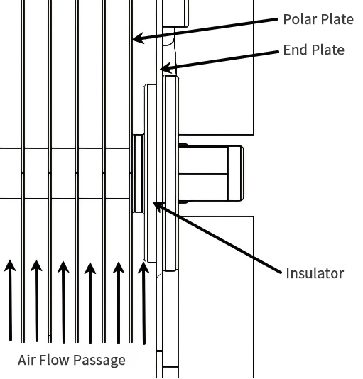
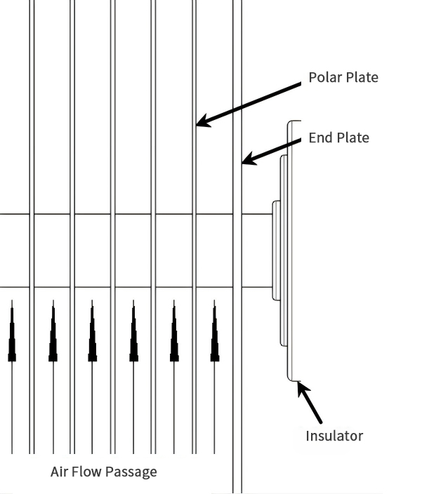
Figure 2.1: Crosssection of conventional ionization chamber
Figure 2.2: Crosssection of optimized ionization chamber
To meet the abovementioned electricfield structural requirements, ceramics are relocated externally with enhanced voltagewithstanding capability. The key measure to prevent highvoltage breakdown of ceramics is to increase their surface creepage distance. The creepage distance of the original design is 15.72 mm. The towershaped structure, a common commercial insulating solution, can theoretically double creepage distance. However, practical tests show that spatial constraints would force reduction of electricfield channels, resulting in higher resistance, increased air velocity at given airflow rates and deteriorated efficiency. Therefore, a discshaped structure with stepped surface contours is adopted instead. Surface undulations increase creepage distance within limited space, delivering 1.5times higher breakdown resistance than the original design (Figure 2.3).
To avoid outward discharge from highvoltage screws of the electric field, both newlydesigned towershaped and discshaped ceramics enclose highvoltage screws for plate positioning inside ceramic bodies. Protrusions at ceramic tail ends are embedded into outer sheetmetal components for fixation.
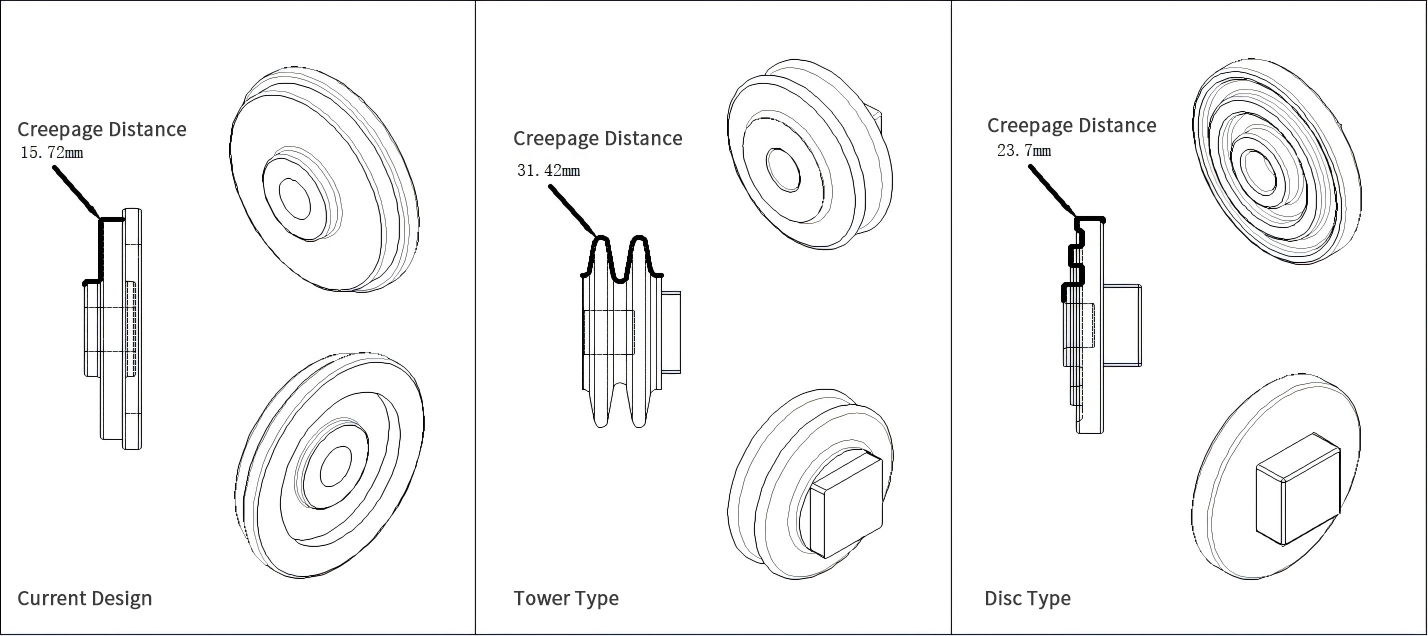
Figure 2.3: Modified profile of ceramic insulator for ionization chamber
In addition, conductive parts between the upper side of the conventional electric field and electrical fixing plates perform satisfactorily under normal conditions. Yet when humid dustladen gas passes through, dust and water vapor accumulate on topside insulators of the ionization chamber. As this is the highvoltage transmission path, arcing and insulator breakdown easily occur in humid and polluted environments and lead to failure of conductive components (Figure 2.4).
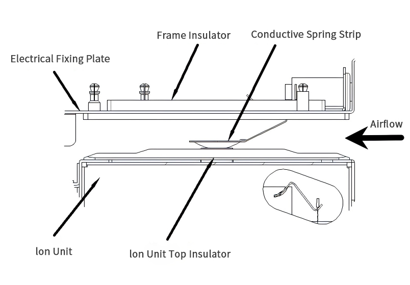
Figure 2.4: Partial schematic of topside connection between conventional ionization chamber and frame
As shown in Figure 2.5, a fixing plate is added upstream of the electric field as a straightforward countermeasure. This effectively solves the abovementioned problem and meanwhile prevents air bypass during filtration by the ionization chamber.
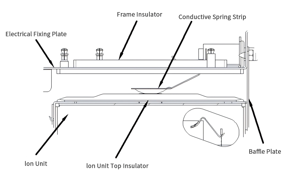
Figure 2.5 (1): Partial schematic of topside connection between optimized ionization chamber and frame
Field feedback indicates that stains and water residues often remain on topside insulators of the ionization chamber after cleaning. Such residues may trigger the same failure modes in subsequent poweron cycles.
For this reason, highvoltage power feeding to the electric field is redesigned to adopt allmetal conductive contact. On one hand, insulator usage is reduced to lower electricfield failure risks caused by insulator anomalies. On the other hand, failures induced by improper onsite operation are avoided (Figure 2.6). Moreover, some commerciallyavailable plastic blocks with poor flame retardancy may burn and generate peculiar odors after breakdown, which severely impairs user experience. Allmetal contact achieves more stable electrical conduction and eliminates such hazards.
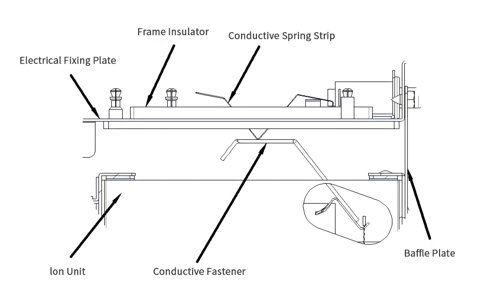
Figure 2.6 (2): Partial schematic of topside connection between optimized ionization chamber and frame
2.3 Insulating Component Design
After implementing the allmetal conductive improvement for electricfield assemblies, insulating blocks on the frame cannot be completely eliminated. Ceramicbased insulating structures are restricted by spatial limits and relatively high costs.
ABS (AcrylonitrileButadieneStyrene copolymer), a thermoplastic polymer, is widely used for insulators in commercial electrostatic filters but tends to soften under sustained hightemperature conditions. BMC (Bulk Molding Compound), a highperformance thermoset composite material, is selected as an alternative. It retains its properties under continuous hightemperature exposure. This material is chosen to resist hightemperature buildup from sustained arcing and breakdown events when the equipment operates at 6.6 kV under humid conditions.
Combustion and energized spray tests are carried out for preliminary screening. Both materials are V0 flameretardant grade, yet BMC delivers superior performance in combustion tests. Furthermore, spray tests are performed under constant 6.6 kV (100 % RH, to accelerate breakdown occurrence). After onehour testing, obvious scorch marks appear on ABS insulator surfaces and conductive loops are detected via multimeter, whereas BMC blocks show no noticeable changes.
Under identical test conditions, BMC blocks are further tested for 4 working days (32 hours in total). Only faint grey scorch marks are observed on block surfaces.
Test results verify that BMC insulating blocks are more suitable than ABS for electrostatic filters operating in humid environments. Corresponding structural design for frame insulating blocks is shown in Figure 2.7 to match the configuration in Figure 2.6.
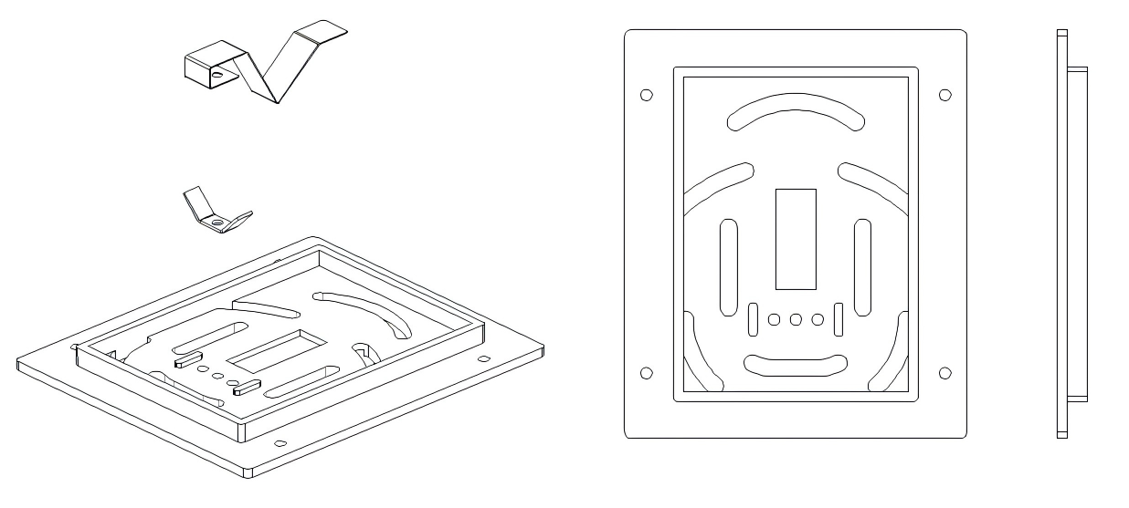
Figure 2.7: Schematic of optimized frame insulating block
3. Laboratory and Field Validation
Products developed according to the above schemes are shown in the partial exploded view in Figure 3.1.
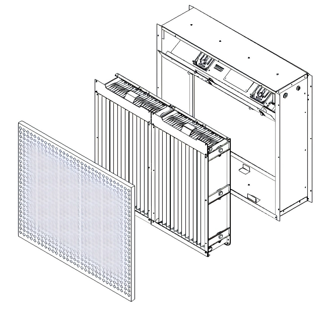
Figure 3.1: Partial exploded rendering of complete unit
3.1 Overall Equipment Validation Tests
Threemonth comparative powerconsumption tests are conducted on complete units.
Figure 3.2 presents the operating curve of the optimized unit. The validation period includes rainy weather conditions. In humid environments, power drops due to arcingtriggered voltage reduction and rebounds after relative stabilization. The overall operating curve remains comparatively stable throughout the test. By contrast, the preimprovement operating curve (Figure 3.3) shows multiple powerdrop segments caused by temporary equipment shutdowns during repeated arcing, which leads to largemagnitude purificationefficiency fluctuations in practical operation.
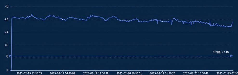
Figure 3.2: Laboratory powermeasurement curve (1)
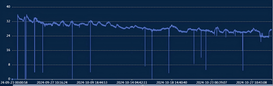
Figure 3.3: Laboratory powermeasurement curve (2)
Windtunnel tests are performed on both original and optimized units. Owing to the baffle added at the front end of the redesigned ionization chamber, resistance increases moderately compared with the original version (Figure 3.4). Nevertheless, air bypass across filters is effectively suppressed, bringing about a 3 %5 % improvement in overall purification efficiency (Figure 3.5).
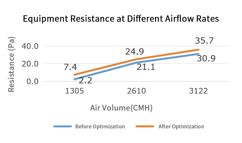
Figure 3.4: Laboratory resistanceversusairflowrate test curves Figure
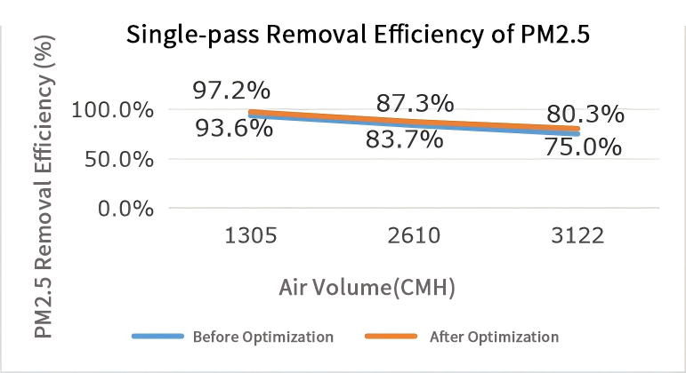
3.5: Laboratory efficiencyversusairflowrate test curves
4. Conclusion
Supported by the above improvement schemes, experimental test data and realworld field applications, the upgrades described in this paper target electrostatic filter deployment inside airhandling units under humid conditions. They effectively enhance electrostaticfilter stability and equip the equipment with selfprotective lowpower operating capability in humid environments. Purification performance is maintained during equipment operation, which plays a vital role in reducing subsequent maintenance workload.
Although electrostatic precipitator technology is relatively mature, further research and development on filtration equipment are still required to adapt to diverse user demands, satisfy special onsite conditions and strengthen product market competitiveness. This paper mainly introduces preliminary improvements derived from practical field feedback to enable sustained and stable operation of electrostatic filters under harsh working conditions. Only humidenvironment scenarios are analyzed in this work. Future research shall expand the scope of harshcondition studies to cover hightemperature, lowtemperature and other operating environments.